EcoBIM 382/1
The EcoBIM 382/1 add-in allows you to calculate the electric consumption of your ventilation systems, according to th SIA 382/1 norm (2014 version). The calculation can also be done with the SIA norm 380/4 (2006 version).
The add-in calculates also the limit and target values, so that you can verify if your systems comply with the norm.
A calculation report can be exported, in a .PDF format, listing:
- The spaces and their electric consumption
- The ventilation systems and their characteristics
- The list of mechanically ventilated spaces
- The list of spaces that are not naturally ventilated
- The information related to the EN-101d form
This report can be used for your building permits, when the local regulation requires it. If the local regulation asks only for the EN-101d form, the information related to it can be manually entered in the Excel file made available by the Cantons.
The values of electric consumption are calculated from the following items:
- Spaces areas
- Spaces categories
- Spaces airflows
- Ventilation systems characteristics (airflows, type, command)
EcoBIM 382/1 uses fictitious ventilation systems, only existing in the add-in. Hence, you do not need to define ventilation systems in your Revit model to use EcoBIM 382/1.
Preparing Your Model and Managing Revit Options
Creating Spaces
EcoBIM 382/1 makes use of the existing spaces in your Revit model. It is thus necessary that you define the spaces that you want to see in the EcoBIM interface beforehand.
More generally, it is recommended to create all the spaces of the model before using the EcoBIM add-ins as defined in the official documentation.
Info
Once the spaces are created, it is recommended to name them from the Revit interface so that you can quickly identify them in the EcoBIM interface. It is however possible to name the spaces from the EcoBIM interface and to use the display feature to locate these spaces in the model.
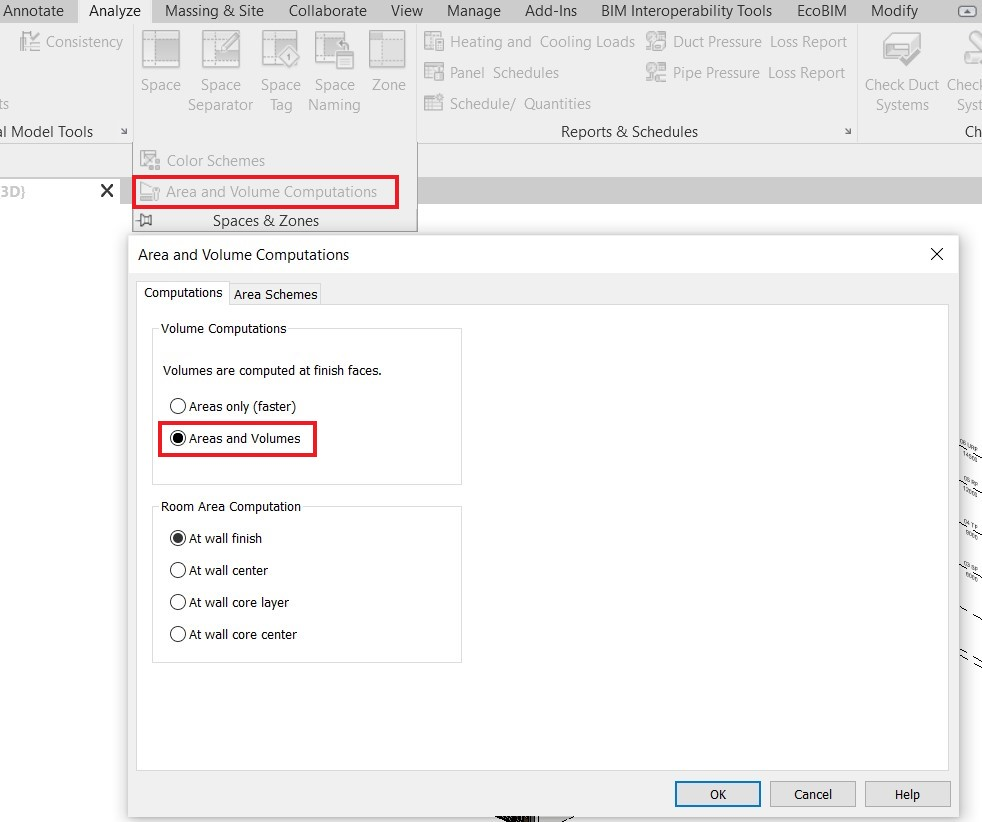
Areas and Volumes Display Options
For information purposes, EcoBIM 382/1 displays the volume of the spaces and
the zones in the parameters pages.
For this information to display correctly, you must enable volume computation
available from the tab Analyze >Spaces and Zones >
Area and Volume Computations:
Using EcoBIM 382/1
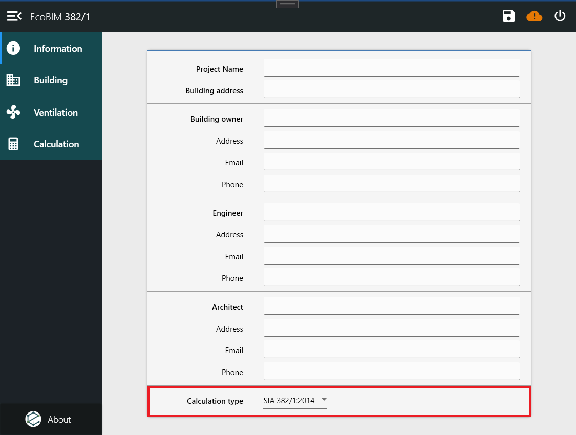
Defining the Reference Norm
EcoBIM 382/1 allows you to calculate the electricity consumption according to the former SIA norme 380/4, 2006 version. Several Cantons accept or demand the use of this norm to comply with the local regulation.
The choice of the norm is done at the bottom of the page Information, thanks
to the available options in the field Calculation type.
The norms differ on the following points:
- Use of the 2006 version of SIA 2024 Technical Standard (SIA norm
- 380/4:2006) or 2015 (SIA norm 382/1:2014). The differences are found in
- the airflows, occupancy, limit and target values.
- Limit and target values of fans specific power depend on each norm.
You can change the reference norm at any moment. A rule is automatically applied to the spaces categories when you change the reference norm.
Changing form the SIA norm 380/4:2006 to the SIA norm 382/1:2014:
| SIA 380/4:2006 | 382/1:2014 |
|---|---|
| Living room, bedroom | Collective housing |
| Furniture retail | Furniture, DIY and garden shop |
| SuperMarket | Food retail |
| Bix box store | Special retail |
Changing form the SIA norm 382/1:2014 to the SIA norm 380/4:2006:
| SIA 382/1:2014 | 380/4:2006 |
|---|---|
| Collective housing, Individual housing | Living room, bedroom |
| Special retail | SuperMarket |
| Laboratory | Light production |
| Clearance area 24h/24, Stairwell | Clearance area |
| Kitchen, floor kitchen | Kitchen |
Preparing your Zone and Spaces
For basic controls and features that relate to EcoBIM add-ins, refer to the Base features.
Info
Launching EcoBIM 382/1 displays the zones and spaces of your model, as well as their stored data. If your model does not have any zones, you can create them from the add-in.
Create as many zones as necessary, according to your need (for instance by
category, storey, or technical installations). When exporting the results, the
spaces in the Remaining spaces will appear in the list of naturally
ventilated spaces. Therefore, the spaces outside of the Energy Reference
Surface (ERS) can be in this list.
To define characteristics for zones and spaces, select one or the other to display the properties frame.
Warning
When your rename a zone or space from EcoBIM, such an element gets instantly renamed in Revit. On the other hand, if the zone or space is renamed from Revit, the element is not updating in the EcoBIM add-in, for the parameters are initialized when displaying the main interface. Therefore, if you want to see these changes, you have to close then reopen EcoBIM. We recommended renaming zones and spaces directly from EcoBIM for simplicity.
Info
EcoBIM 382/1 keeps in memory the information you have entered in your zones and spaces (ventilation systems, airflows). When you activate or deactivate a toggle button, the last information you have entered appears.
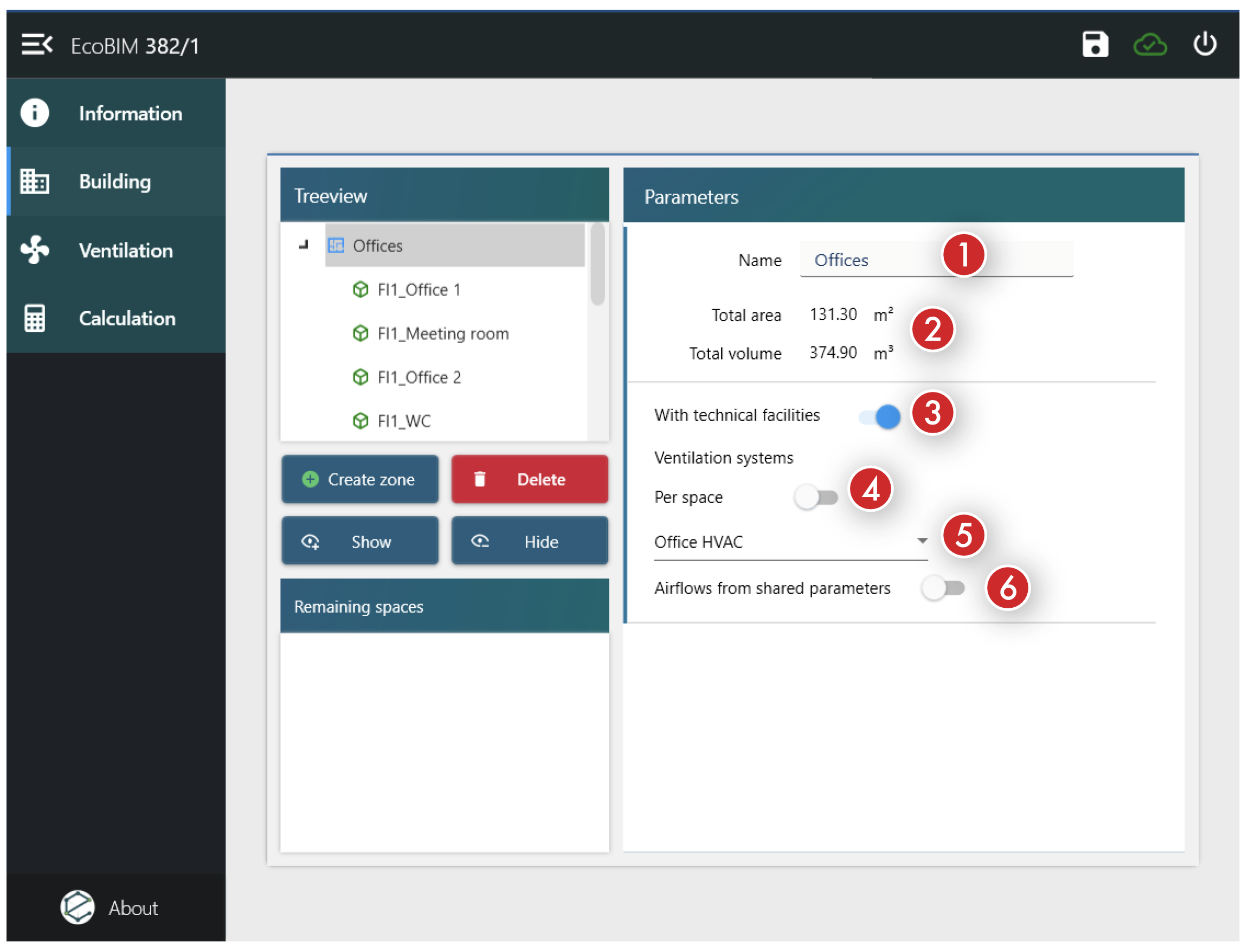
Zones Settings
The Zone page has the following parameters:
Name: Name of the zone that corresponds to the name displayed in Revit.Area/Volume: The areas and volumes that correspond to the sum of the areas and volumes from the spaces. These values are automatically updated when you add or remove spaces from a zone.With technical facilities: This property allows you to specific whether a zone has a mechanical ventilation system. This property is activated by default. If you deactivate it, you cannot specify the HVAC system for a zone, and all the zones and spaces will be considered to be naturally ventilated.- Ventilation systems -
Per space: When deactivated, this setting allows you only to define a ventilation system at the zone level. When enabled, you must define ventilation systems at the space level. - Ventilation systems - HVAC list: This list displays the ventilation systems
that are available in the
Ventilationpage. Choosing a ventilation system associates all the zone spaces to this system. This field is available only if the previous property,Per space, is deactivated. - Airflows from shared parameters : This property sets the flow rates of the spaces according to their values in their shared parameters.
Spaces Settings
The Space page has the following parameters; define these properties for
all spaces in your model, except for the ones in the Remaining spaces
category.
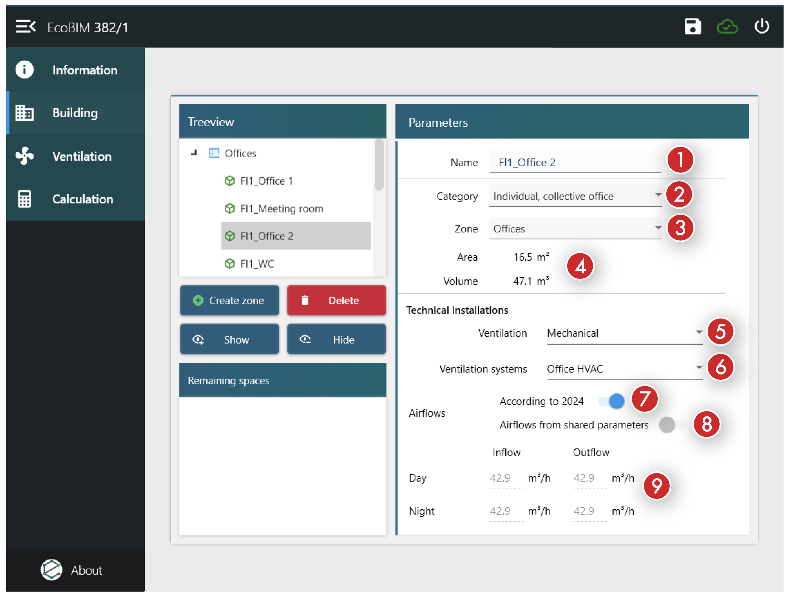
Name: Name of the space as defined in the model; renaming a space from the add-in also renames the space in Revit.Category: Space category as defined in the Technical Standard 2024, 2015 or 2006 version.Zone: Zone in which spaces reside. Changing the zone assigns the space to that zone.Area/Volume: Area and volume of the space, computed from the model.- Technical installations -
Ventilation: Allows you to define if the space is mechanically or naturally ventilated. This field is available only if you activate thePer spacesetting for a zone. - Technical installations -
Ventilation systems: Allows you to define which ventilation system is used to ventilate this space. - Airflows -
According to 2024: When you select this property, the add-in automatically calculates airflows in the space, and the fields beneath that setting are deactivated. Deactivate this property if you want to manually input the airflows. - Airflows -
Airflows from shared parameters: When you select this property, airflows are set from Revit shared parameters, and the airflows fields are deactivated. - Airflows - Fields
Inflow,Outflow,Day,Night: Airflows in the space. These airflows are ignored if the space is naturally ventilated. The values are automatically calculated if you enable theAccording to 2024option.
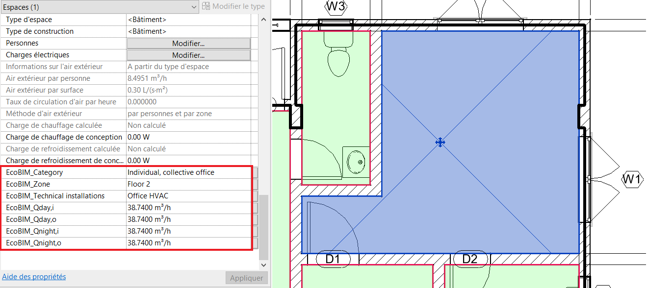
When saving, the shared Revit parameters are overwritten with the
new values at the space level. It is possible to manually change the
airflows. These airflows get imported into the spaces if you select the
Airflows from shared parameters property.
Changing the other fields (Category, Zone, Technical installations) will have no effect, and it is not recommended to change them.
Ventilation Systems
The Ventilation window allows you to create and to set up ventilation
systems (also defined as HVAC).
These ventilation systems are the ones that appear in the drop-down list, at
the zone and space level. Each ventilation system can be configured through
the Data and Parameters pages.
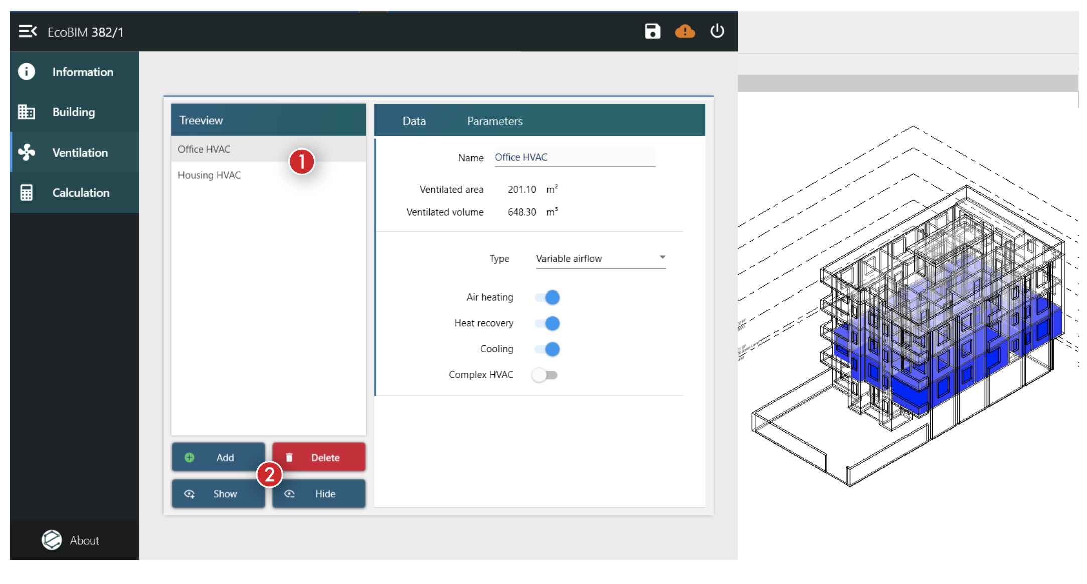
The Ventilation window has the following features:
- List of created ventilation systems
-
A bloc of buttons allowing the following features:
- Adding a ventilation system with the first button. Click it to create
a new HVAC unit. The HVAC unit will appear in the treeview under the name
HVAC+ number of the system. - Deleting a ventilation system with the second button. Click on this button to delete the selected HVAC.
- Showing the HVAC unit with the third button. Click on this button to show the spaces ventilation with the selected HVAC unit.
- Hiding the HVAC unit with the fourth button. Click on this button to reset the display settings, after they have been modified by the previous button.
- Adding a ventilation system with the first button. Click it to create
a new HVAC unit. The HVAC unit will appear in the treeview under the name
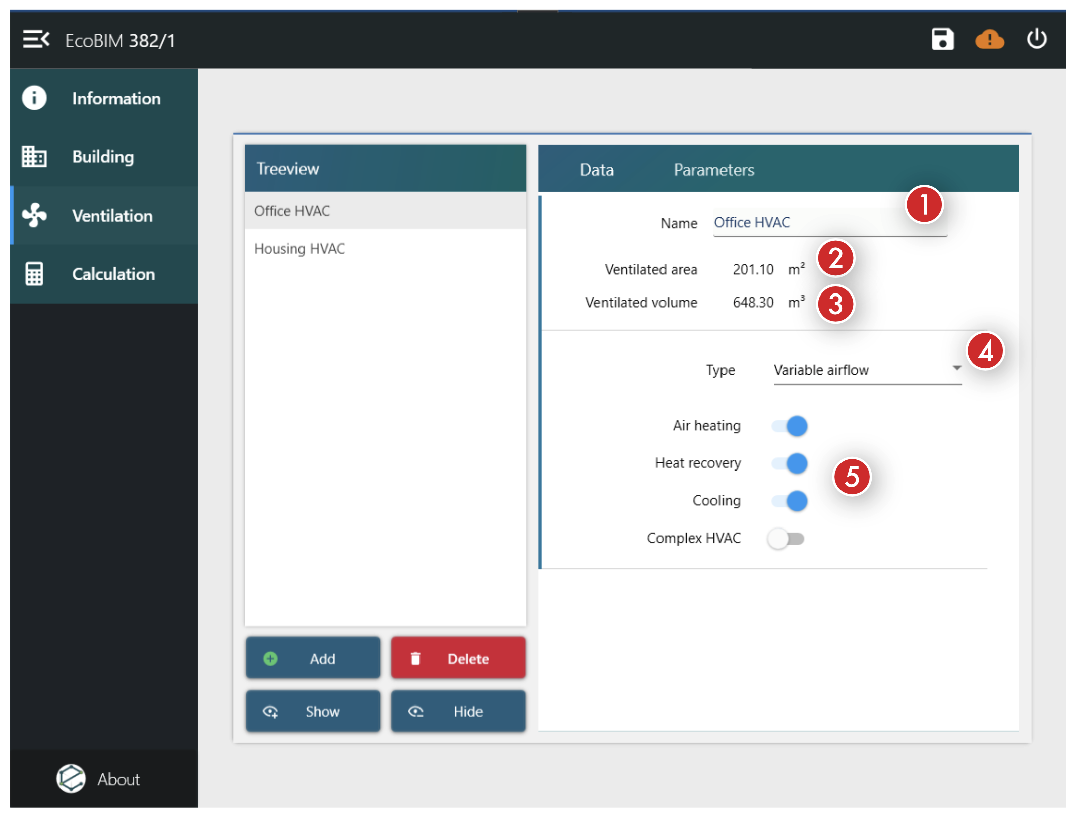
The Data page allows you to define the ventilation system:
- Name of the HVAC unit.
- Ventilated area: Total area of the spaces that are mechanically ventilated by the HVAC unit.
- Ventilated volume: Total volume of the spaces that are mechanically ventilated by the HVAC unit.
-
Type: You can define different types, corresponding to the intented operation of the system:
- 1 speed: Operation at constant flow
- 2 speeds: Operation at two speeds, controlled according to the occupancy.
- 3 speeds: Operation at three speeds, controlled according to the occupancy.
- Day/Night: Operation at two speeds, according to the time in the day. The day operation runs from 7am to 10pm and the night operation runs from 10pm to 7am.
- Variable airflow: Operation at variable airflow, controlled according to the occupancy.
-
Air treatment parameters, defining the target and limit values of the fans specific power:
Air heating: Activate this property if the HVAC unit has a heating coil.Heat recovery: Activate this property if the HVAC unit has a heat exchanger.Cooling: Activate this property if the HVAC unit has a cooling coil.Complex HVAC: Activate this property if the HVAC is complex, as per the SIA norm 382/1, paragraph 5.7.4.2.
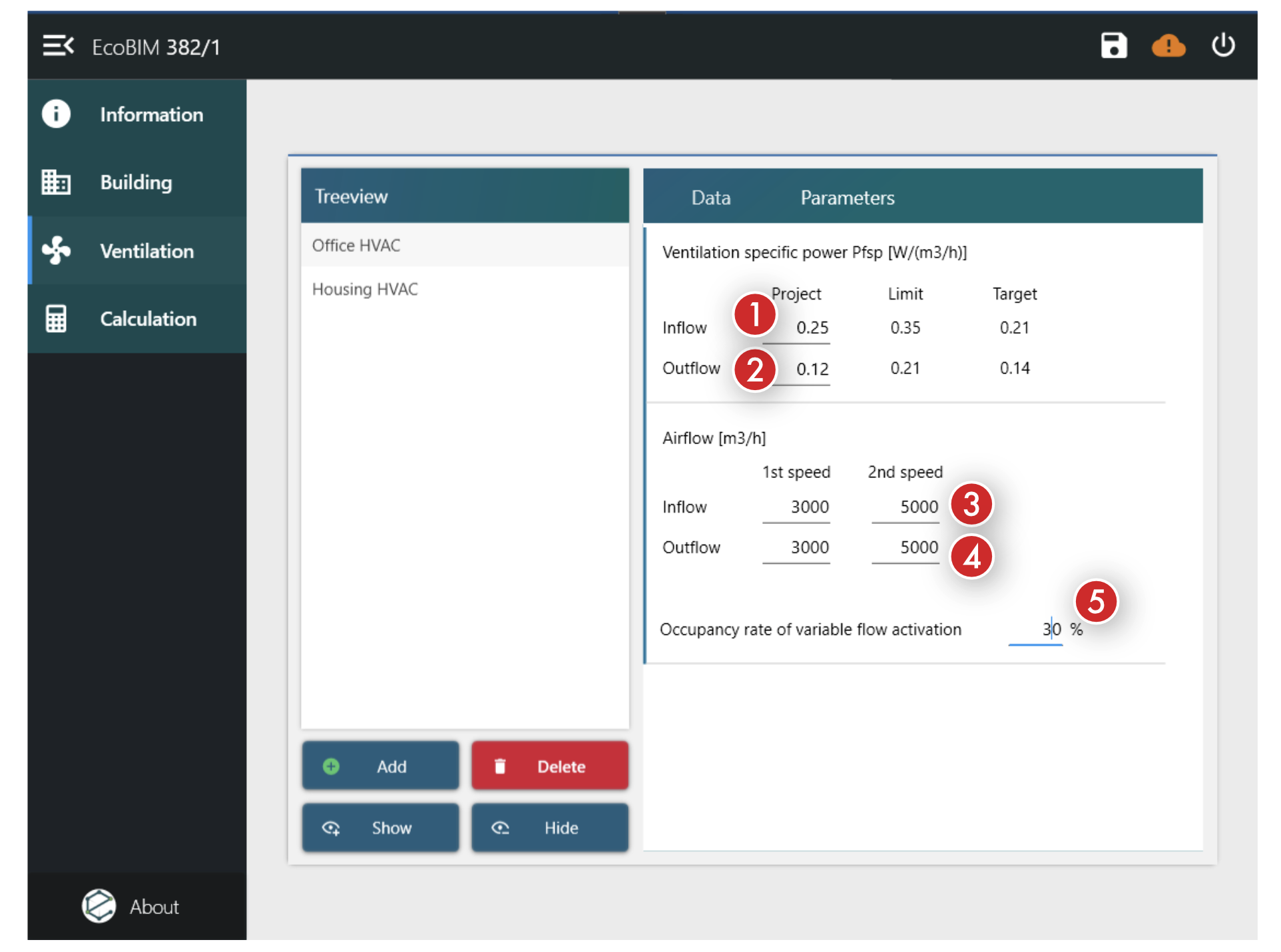
The Parameters page allows you to specify the operation of the ventilation
system:
- Inflow fan specific power: power of the fan in
W/(m3/h) - Outflow fan specific power: power of the fan in
W/(m3/h) - Inflow: airflow entering the room, depending of the system type, in
m3/h - Outflow: airflow leaving the room, depending of the system type, in
m3/h - Occupancy rate of the system speeds activation: Occupancy rate of the building from which the system will go to the next speed.
Calculation
Results
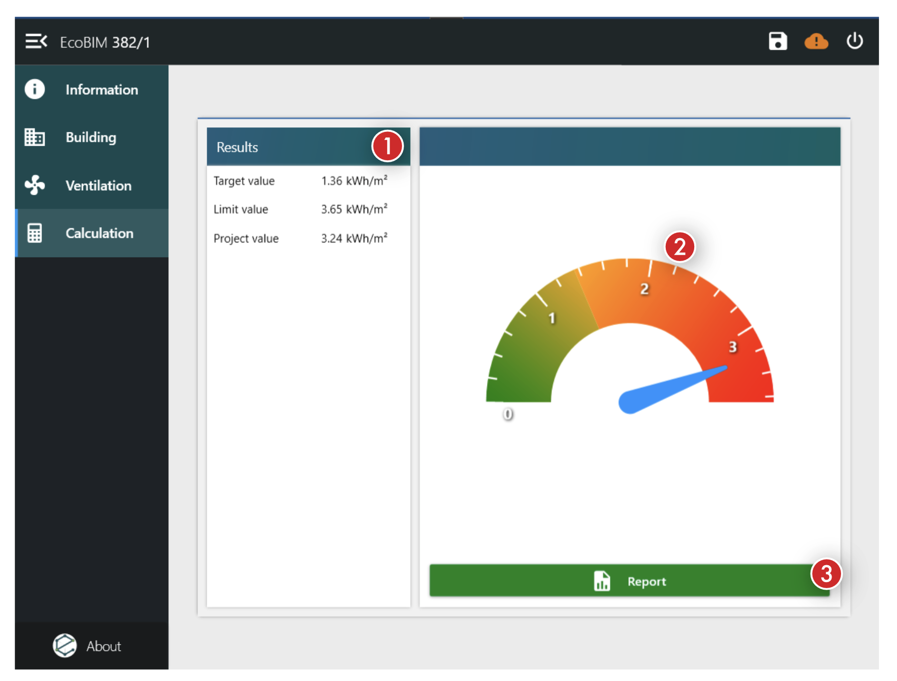
Once all the spaces are set up, you can show the total electricity consumption
of your ventilation systems from the Calculation window.
The window shows only if all the spaces have at least a category, otherwise a window will display listing all the spaces for which the category has not been defined.
This window shows:
- The electricity consumption values (target, limit and project values)
- A dynamic graph showing the electricity consumption
- A
Reportbutton allowing you to export your results in .PDF format
These results are updated whenever a change occurs in the Building or
Ventilation window.
Report
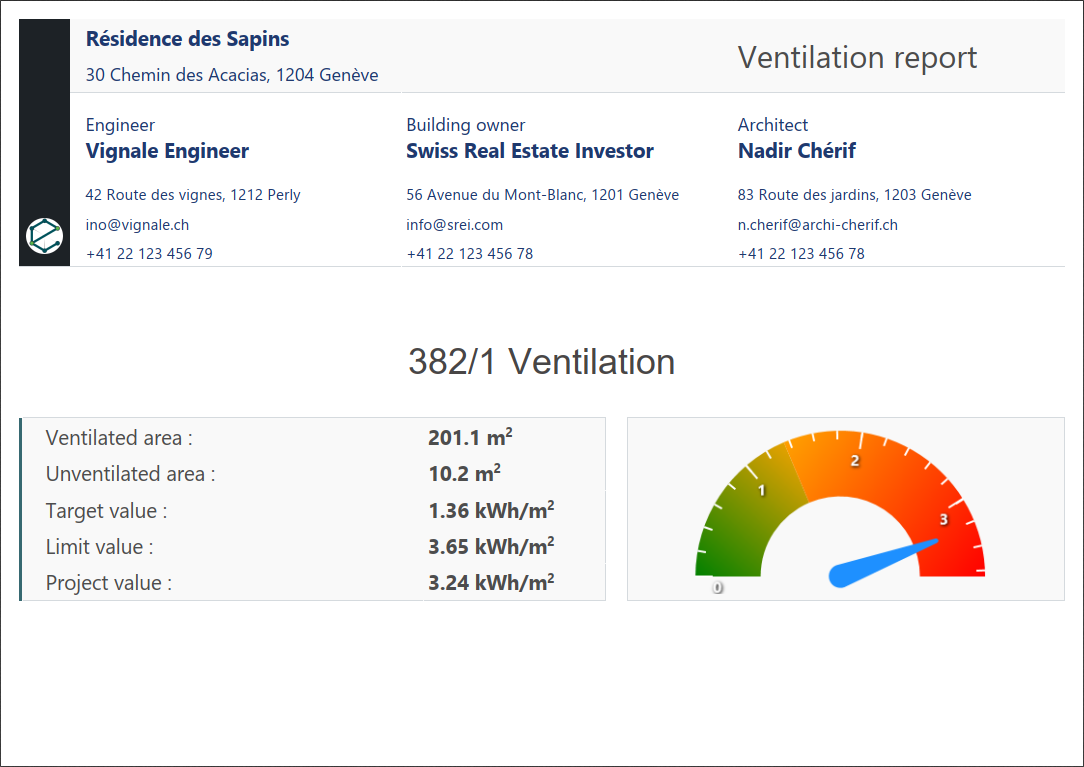
Click the Report button to generate your calculation report.
A Save File dialog opens, asking you to name your file and save it in a
.PDF format.
Info
If a file with the same name exists, a confirmation dialog will open, asking if you want to replace the existing file.
Warning
When exporting your results, make sure that you do not have a file with a similar name already open. If a file with the same name is open, an error window will display and the saving process will fail.
The following pictures show some extracts of a typical report:
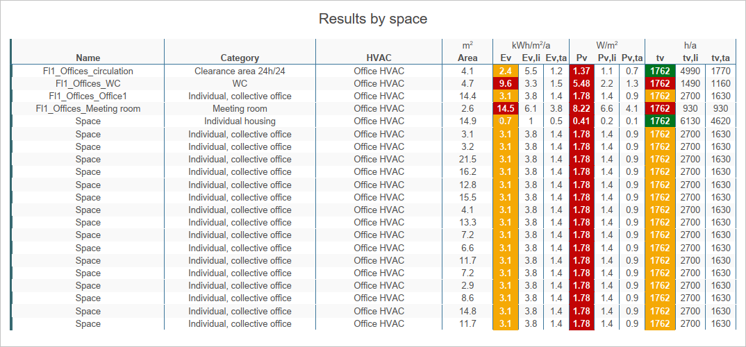
The following columns are presented in the Results by space page:
- Name
- Category
- Ventilation system name (HVAC)
- Area
- Electricity consumption
- Electricity consumption - limit value
- Electricity consumption - target value
- Electric power
- Electric power - limit value
- Electric power - target value
- Full load hours
- Full load hours - limit value
- Full load hours - target value
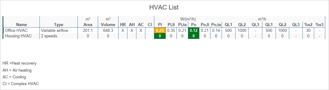
The following columns are presented in the HVAC List page:
- Name
- Operation type
- Ventilated area
- Ventilated volume
- Heat exchanger presence
- Heating coil presence
- Cooling coil presence
- Complex installation
- Inflow fan power
- Inflow fan power - limit value
- Inflow fan power - target value
- Outflow fan power
- Outflow fan power - limit value
- Outflow fan power - target value
- Inflow, 1st speed
- Inflow, 2nd speed
- Inflow, 3rd speed
- Outflow, 1st speed
- Outflow, 2nd speed
- Outflow, 3rd speed
- 2nd speed occupancy rate activation
- 3rd speed occupancy rate activation
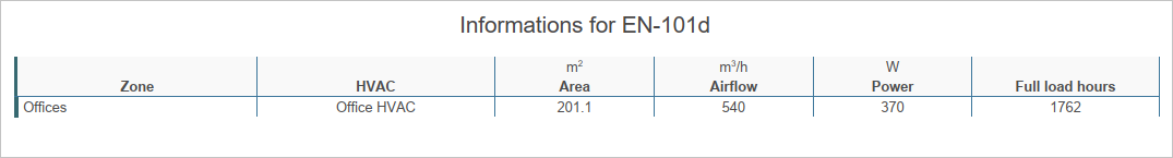
The following columns are presented in the Informations for EN-101d page:
- Zone
- HVAC
- Area
- Zone airflow
- Ventilation power
- Full load hours